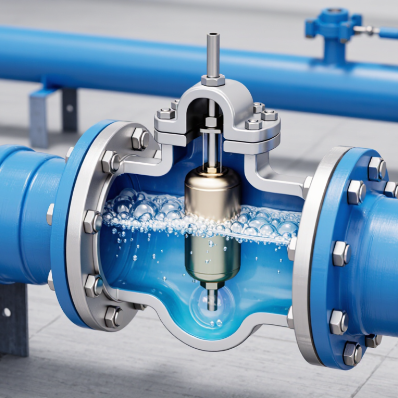
| 1. Air Accumulation | Air naturally collects at high points in a pressurized water or liquid pipeline because air is less dense than the liquid. | The valve remains connected to the pipeline through its inlet. | As air enters the valve chamber, the liquid level inside the chamber falls and the float moves downward. | Air is prepared for automatic discharge instead of remaining trapped in the pipeline. |
| 2. Air Discharge | The accumulated air lowers the liquid level in the valve chamber. | The discharge opening opens. | The float drops away from the outlet mechanism, allowing trapped air to escape through the vent orifice. | Air pockets are removed, helping reduce flow restriction, pressure fluctuations, and measurement errors. |
| 3. Liquid Reaches the Valve | After sufficient air has been released, liquid rises into the valve chamber. | The discharge opening closes automatically. | The float rises with the liquid and presses against the sealing seat or linkage. | Liquid loss is stopped while the pipeline remains pressurized. |
| 4. Continuous Air Release | Small quantities of dissolved or entrained air may separate from the liquid during normal operation. | The small air-release orifice opens and closes as needed. | A float-operated mechanism releases accumulated air whenever the chamber pressure and liquid level permit it. | Air is removed continuously without requiring manual operation or interrupting service. |
| 5. Pipeline Filling | Liquid enters an initially empty or partially empty pipeline and pushes air ahead of it. | A dedicated air-release valve discharges displaced air. | The valve stays open while air lowers the float, then closes when liquid fills the chamber. | Filling can be controlled while limiting the amount of liquid discharged through the valve. |
| 6. Pipeline Draining | Liquid leaves the pipeline and internal pressure may fall below atmospheric pressure. | An air-and-vacuum valve, or combination valve, opens to admit air. | Reduced pressure allows the float to move away from the seat, creating an inlet path for atmospheric air. | Vacuum conditions and potential pipe collapse or structural damage are reduced. |
| 7. Air Under Pressure | When the pipeline is full and pressurized, the air-release mechanism operates against internal line pressure. | The small vent closes when liquid reaches the float. | Line pressure helps maintain the seal, while the float position controls the opening and closing cycle. | Air can be released during normal pressurized operation without opening the pipeline manually. |
| 8. Valve Type Selection | Different pipeline events require different air-flow capacities. | The valve design is selected according to the expected operating condition. | A small-orifice air-release valve handles air released during normal operation; an air-and-vacuum valve handles large air volumes during filling and draining; a combination valve provides both functions. | The valve matches the pipeline’s air-management requirements and operating cycle. |
| 9. Typical Installation Location | Air tends to collect at summits, changes in pipeline elevation, and other high points. | The valve is installed at a suitable high point and connected to the pipeline. | The location allows buoyant air to reach the valve chamber while the valve remains accessible for inspection and maintenance. | Air removal is more effective, and routine servicing is easier. |
| 10. Main Components | The valve must separate air from liquid while responding to changes in liquid level and pressure. | Internal parts move automatically without an external power source. | Common components include a body, float, seat, discharge orifice, cover, and sealing elements. The exact arrangement depends on the valve design. | A simple buoyancy-based mechanism provides automatic air management. |
| 11. Important Design Factors | Air-flow requirements vary with pipe size, filling and draining rates, pressure, liquid type, and pipeline profile. | The valve size and type must be selected for the specific system. | Engineers consider air inflow and outflow capacity, operating pressure, materials, temperature, chemical compatibility, and maintenance requirements. | Correct sizing helps prevent inadequate air release, excessive pressure loss, leakage, and water hammer-related problems. |
| 12. Maintenance Considerations | Debris, scale, corrosion, or damaged seals can interfere with float movement and seat sealing. | The valve should be inspected and serviced according to system conditions and applicable maintenance procedures. | Maintenance commonly includes checking the float, cleaning the orifice and seat, inspecting seals, and confirming that isolation arrangements operate correctly. | Reliable automatic operation and reduced risk of leakage or blockage are maintained. |


 © Copyright 2020 Tianjin Tanghaidongyang Valve Co., Ltd. All Rights Reserved.