| Normal system operation | 11 kV distribution system; approximately 6.35 kV RMS phase-to-ground | High-resistance standby | Very small capacitive and resistive leakage current, commonly in the microampere-to-low-milliampere range | Close to the normal phase-to-ground system voltage | Metal-oxide varistor blocks significant conduction while continuously monitoring the line voltage | Normal power flows to the load without material energy absorption by the arrester |
| Continuous operating voltage limit | Representative MCOV: 8.4 kV RMS for a medium-voltage arrester used on an 11 kV system | Stable and non-linear | Leakage remains limited when the applied voltage is below the continuous operating voltage limit | Voltage remains within the arrester’s intended continuous-duty range | The polymer-housed arrester remains connected between the line and ground without interrupting normal service | Reliable long-term operation, provided the system voltage and grounding arrangement are correctly selected |
| Temporary overvoltage | Approximately 1.2–1.4 per-unit voltage caused by faults, load rejection, or grounding conditions; duration may range from cycles to seconds | Increased conduction | Higher leakage current than during normal operation | Voltage is limited, but the arrester may heat if the overvoltage is excessive or prolonged | The varistor conducts progressively as voltage rises; its thermal capability and temporary-overvoltage rating determine safe withstand time | The system may remain protected if the temporary overvoltage is within the arrester’s specified capability |
| Lightning or switching surge arrival | Fast transient impulse; a common test waveform is 8/20 microseconds | Low-resistance conduction | Surge current may range from several hundred amperes to several kiloamperes | Representative residual voltage: approximately 20–35 kV for a medium-voltage unit, depending on design and test current | The zinc-oxide varistor changes rapidly from a high-resistance state to a highly conductive state and diverts surge current to ground | Equipment insulation is exposed to a lower, controlled voltage than the incoming surge |
| Moderate switching surge | Typical impulse current of approximately 0.5–2 kA, depending on the network and switching event | Controlled conduction | Hundreds of amperes to a few kiloamperes | Usually below the arrester’s lightning-impulse residual-voltage level | The arrester absorbs and diverts transient energy while limiting the crest voltage at the protected equipment | Reduced risk of insulation stress caused by circuit-breaker operation, capacitor switching, or fault clearing |
| High-current lightning discharge | Impulse current can reach several kiloamperes; actual severity depends on exposure, shielding, and grounding | Heavy conduction and energy absorption | Common arrester test levels include 5 kA or 10 kA using an 8/20 microsecond current waveform | Clamping voltage rises with discharge current because the varistor has a non-linear voltage-current characteristic | The arrester conducts the impulse to ground while the polymer housing provides external insulation and environmental sealing | Transient voltage is clamped to a level selected below the protected equipment’s insulation withstand level |
| After the surge ends | System voltage returns to its normal operating value | Returns to high-resistance standby | Surge current stops; only normal leakage current remains | Returns close to the system phase-to-ground voltage | The varistor stops conducting heavily without requiring a spark gap to extinguish an arc | Protection is automatically restored for subsequent transients, assuming no thermal or electrical damage occurred |
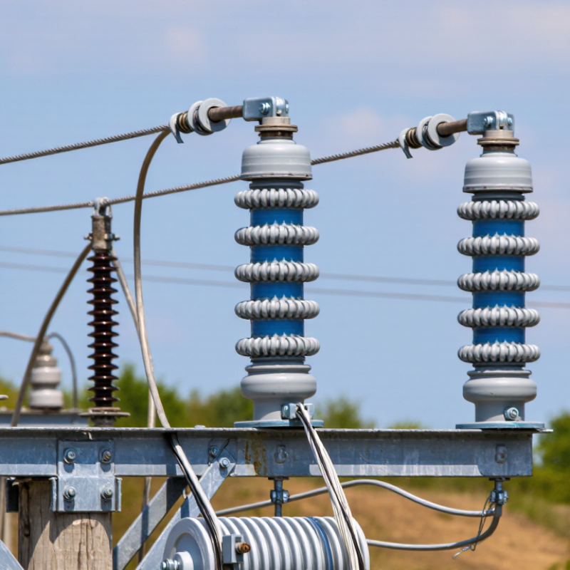
| Severe or repeated overload | Excessive temporary overvoltage, repeated high-energy surges, or an incorrectly selected arrester | Thermal stress or failure condition | Persistent high leakage current may produce internal heating | Protection performance can deteriorate, and the arrester may no longer clamp voltage correctly | An integrated disconnector may separate a failed unit from the system; the polymer housing is designed to reduce explosive fragmentation compared with brittle housings | The arrester must be inspected and replaced after confirmed failure or when diagnostic indicators show unacceptable degradation |
| Grounding and installation path | Short, low-inductance connection between the line terminal, arrester, and earth | Essential for effective protection | Surge current is directed through the arrester and grounding conductor | Every metre of extra lead length can add inductive voltage during a fast surge | Correct phase-to-ground connection, short leads, appropriate clearances, and a low-impedance earth path minimize the voltage appearing at the equipment | Better coordination between arrester residual voltage and the protected equipment’s insulation withstand rating |


 © Copyright 2020 Tianjin Tanghaidongyang Valve Co., Ltd. All Rights Reserved.