| Basic Definition and Electrical Function |
| Transformer type | Single-phase transformer | A static electrical device that transfers alternating-current energy between circuits through electromagnetic induction. |
| Primary supply | 120 V or 240 V AC | The primary winding receives the input voltage. The exact voltage depends on the connection and the transformer design. |
| Secondary output | 120 V, 240 V, or 120/240 V AC | A center-tapped 120/240 V secondary can provide 120 V from either line to neutral and 240 V between the two line terminals. |
| Operating frequency | 50 or 60 Hz | The rated frequency must match the intended power system because frequency affects core flux, heating, and magnetizing current. |
| Energy transfer method | Mutual electromagnetic induction | An alternating current in the primary creates changing magnetic flux in the core, inducing voltage in the secondary winding. |
| Electrical isolation | Usually provided | In an isolated transformer, the primary and secondary windings are electrically separate while still coupled magnetically. |
| Voltage, Turns, and Current Relationships |
| Ideal voltage ratio | Vp/Vs = Np/Ns | The primary-to-secondary voltage ratio is approximately equal to the primary-to-secondary turns ratio. |
| Example turns ratio | 2:1 for 240 V to 120 V | A winding arrangement with approximately twice as many primary turns as secondary turns can reduce 240 V to about 120 V, subject to losses and regulation. |
| Ideal current relationship | Ip/Is = Ns/Np | For an ideal transformer, the lower-voltage winding carries higher current for the same apparent power. |
| Apparent power rating | VA or kVA | Transformer capacity is normally stated in volt-amperes because both voltage and current determine winding and core loading. |
| Typical small-unit ratings | 50 VA to 5 kVA | Small single-phase units commonly serve control circuits, lighting, appliances, instrumentation, and low-power distribution applications. |
| Voltage regulation | Load-dependent voltage change | The secondary voltage generally falls as load current increases because of winding resistance and leakage reactance. |
| Core Parts and Their Functions |
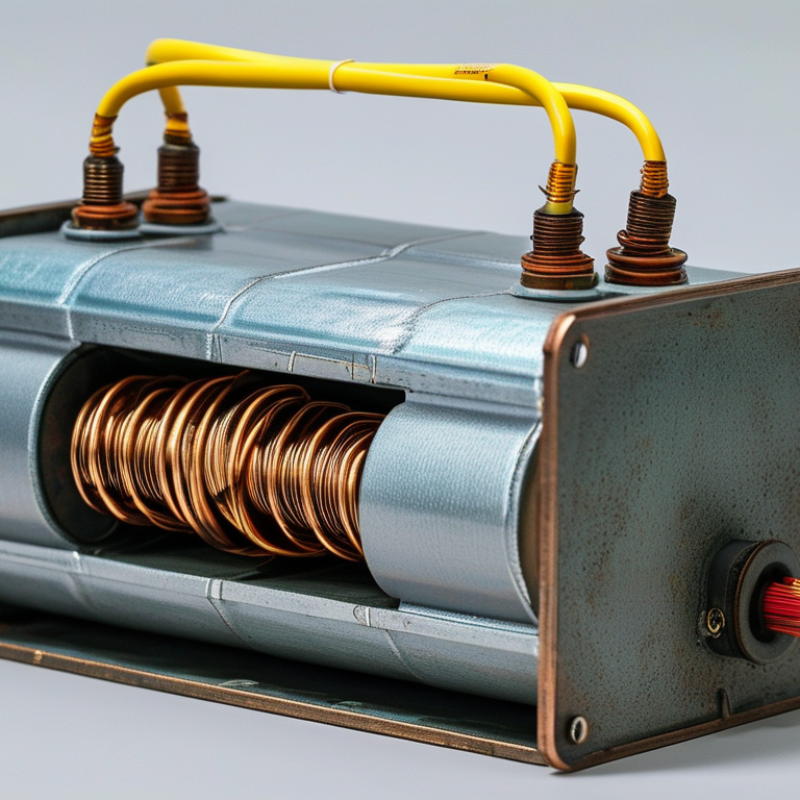
| Magnetic core | Laminated electrical steel | Provides a low-reluctance path for alternating magnetic flux. Laminations reduce eddy-current losses. |
| Primary winding | Insulated copper or aluminum conductor | Connects to the input supply and establishes the alternating magnetic flux in the core. |
| Secondary winding | Insulated copper or aluminum conductor | Receives induced voltage from the magnetic field and supplies power to the connected load. |
| Center tap | Optional neutral connection | A center-tapped secondary divides a 240 V winding into two approximately equal 120 V sections. |
| Winding insulation | Electrical insulation system | Separates turns, layers, and windings to prevent short circuits and withstand the specified voltage stress. |
| Bobbin or winding former | Insulating support structure | Supports and positions the windings while maintaining required clearances and insulation distances. |
| Terminals and leads | Input, output, and optional tap connections | Provide external electrical connections and identify the correct polarity, voltage, and grounding arrangement. |
| Enclosure | Open-frame or enclosed housing | Protects energized parts and may assist with cooling. The enclosure type must suit the installation environment. |
| Operating Characteristics and Safety |
| No-load secondary voltage | May exceed the nameplate voltage | Manufacturers may design for voltage drop under load, so the measured no-load voltage can be higher than the rated loaded value. |
| Efficiency | Typically high, load-dependent | Efficiency is reduced by copper losses in the windings, core losses, leakage flux, and auxiliary losses. |
| Main losses | Copper loss and core loss | Copper loss increases with load current, while hysteresis and eddy-current losses occur in the magnetic core during AC operation. |
| Grounding | System-dependent | Grounding and bonding must follow the applicable electrical code and the transformer’s wiring diagram; a neutral is not automatically the same as equipment ground. |
| Overcurrent protection | Required according to installation rules | Fuses or circuit breakers protect the transformer and conductors from excessive current and fault conditions. |
| Common applications | Lighting, control power, isolation, and small distribution | Single-phase transformers are used where the source and load are single-phase and where voltage conversion or isolation is needed. |
| Nameplate information to verify | Primary voltage, secondary voltage, frequency, VA/kVA, temperature class, and wiring diagram | These ratings determine whether the transformer is suitable for the intended supply, load, environment, and installation method. |


 © Copyright 2020 Tianjin Tanghaidongyang Valve Co., Ltd. All Rights Reserved.