Certificates

Certificates

What Is a Hydraulic Check Valve and How Does It Work?

A hydraulic check valve allows fluid to move in one direction and helps prevent unwanted reverse flow. It is a small component, but its position can shape how an entire hydraulic circuit behaves. In a common spring-loaded design, forward pressure pushes a poppet or ball off its seat. Fluid then passes through the valve. When pressure falls or reverses, the spring and fluid pressure return the sealing element to its seat. Reverse flow is blocked. The mechanism sounds straightforward, yet real systems add important details.

This introduction explains the valve’s main parts, operating principle, common configurations, and role in equipment such as presses, lifts, and mobile machinery. It also considers practical choices, including cracking pressure, flow capacity, pressure drop, installation direction, and fluid cleanliness. A valve that works well on a diagram may behave differently when exposed to cold oil, contamination, or repeated pressure spikes. Small details matter. Correct selection depends on the circuit, manufacturer specifications, and operating conditions—not on the valve’s name alone. A check valve does not automatically regulate pressure or guarantee a leak-free seal. Wear, debris, and incorrect installation can affect performance. Understanding these limits helps readers evaluate where a hydraulic check valve fits, what it can protect, and when the wider system needs closer inspection.

What Is a Hydraulic Check Valve and How Does It Work?

What a Hydraulic Check Valve Is and Its Purpose

A hydraulic check valve allows fluid to flow in one direction and resists flow in the opposite direction. Its purpose is to preserve a circuit’s intended flow path, prevent reverse flow, and help retain pressure in selected parts of a system.

Inside, a spring presses a ball or poppet against a seat. Forward pressure lifts it; reverse pressure pushes it closed. Simple in principle.

That matters when a pump stops or another circuit branch changes pressure. The valve can help prevent a cylinder from drifting, but it is not a substitute for a properly engineered load-holding arrangement. Seal wear, contamination, and incorrect sizing can still cause leakage.

A useful wider context comes from the U.S. Department of Energy’s 2006 Improving Pumping System Performance sourcebook: pumping systems use nearly 20% of global electricity, though this figure does not measure hydraulic check-valve performance. The report highlights why controlling fluid flow matters, but the valve’s actual effect depends on the whole circuit.

ISO 4413:2010 also sets safety principles for hydraulic systems, including managing pressure-related hazards. Always check the valve’s rated pressure, flow direction, and opening pressure against the application. Small details matter.

Core Components and Their Functions

What Is a Hydraulic Check Valve and How Does It Work?

Core Components and Their Functions

A hydraulic check valve lets fluid move in one direction and resists flow in the opposite direction. Its compact body contains an inlet, an outlet, and an internal sealing element. That element may be a ball, poppet, or disc, depending on the valve design. A machined seat gives it a surface to seal against. Small imperfections or debris on that surface can allow leakage.

A spring usually presses the sealing element toward its seat when there is little pressure. When inlet pressure rises enough, it pushes the element away and opens a path for fluid. This opening threshold is called the cracking pressure. It matters when selecting a valve for a circuit with limited pump pressure. Simple, but not effortless.

If pressure reverses, fluid pushes the element back against the seat, helping block reverse flow. Some designs use a pilot piston to release the seal when a separate control pressure is applied. The body must withstand system pressure, while ports and seals help maintain a secure connection. In practice, installation direction matters: the flow arrow should match the intended path. A valve drawing can make the mechanism seem foolproof, but wear, contamination, and incorrect sizing still affect performance.

How a Hydraulic Check Valve Opens

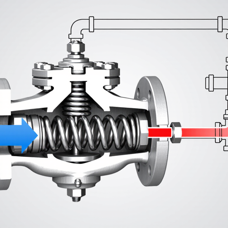
This example shows a spring-loaded check valve with an illustrative cracking pressure of 0.5 bar. The valve opens when forward pressure differential reaches that threshold and closes to resist reverse flow. Actual cracking pressure varies by valve design.

Core components: The valve body guides the flow; the poppet or ball seals against the seat to block reverse flow; and the spring holds the valve closed until sufficient forward pressure is applied.

How the Valve Opens and Closes

A hydraulic check valve allows oil to travel in one direction and resists flow in the other. Its opening action depends on pressure, not an electrical signal. Inside, a ball or poppet rests against a seat, often held there by a small spring. When inlet pressure rises enough to overcome the spring force and pressure on the outlet side, the moving element lifts from the seat. That is the threshold. Then flow begins. In a cutaway, the opening may look tiny, but it lets oil pass through the valve body and into the next section of a circuit.

When the pressure difference drops, the spring pushes the ball or poppet back toward its seat. Reverse pressure helps press it closed, limiting oil from flowing backward. Small parts matter. A worn seat, contamination, or a weak spring can prevent a clean seal, so a valve may leak internally even when its exterior looks sound. In a real circuit, closure is not always neat: pressure can fluctuate, and the moving part may chatter if flow or valve sizing is unsuitable. Listening for unusual vibration and checking pressure readings can help identify trouble, though those clues alone do not confirm the cause. The valve’s response also depends on its cracking pressure and the system’s operating conditions.

Common Types of Hydraulic Check Valves

Hydraulic check valves come in several designs, each controlling reverse flow in a different way. A ball check uses a small ball that lifts from its seat when fluid flows forward. Reverse pressure pushes it back into place. It is simple and compact, but dirt or a worn seat can prevent a tight seal. Poppet checks use a shaped plug instead of a ball. Their guided movement can provide a firm seal and handle substantial flow, depending on the design. Small details matter.

Pilot-operated check valves add a control port. Pressure from another line helps open the valve, allowing a cylinder to move when commanded while resisting reverse flow otherwise. They are often used for load holding, but they are not magic: leakage, trapped pressure, and incorrect pilot sizing can affect performance. A suspended load needs a properly engineered system, not just one valve.

Dual pilot-operated checks control both sides of a double-acting cylinder. They can help hold position, though they may also trap fluid and make troubleshooting less straightforward. Inline and cartridge versions describe how a valve is installed, rather than how it works. In practice, that distinction is easy to overlook. Match the valve’s pressure, flow, cracking pressure, and fluid cleanliness requirements to the circuit, then verify behavior under real operating conditions.

Where Hydraulic Check Valves Are Used

Hydraulic check valves appear wherever fluid must move in one direction while resisting reverse flow. In a mobile excavator, they can help hold a raised boom when the pump stops. In a forklift, they may help keep a loaded mast from settling unexpectedly. The valve opens when pressure pushes fluid through its permitted path; reverse pressure seats the internal poppet or ball and restricts flow. Small parts matter.

Industrial equipment uses check valves in hydraulic power units, presses, clamping circuits, and lubrication lines. A check valve near a pump can reduce reverse flow when the system shuts down. In a machine tool, one placed within a circuit may help preserve pressure at a clamp while other functions operate. Placement depends on the circuit design, not just the machine type. Not always obvious.

On agricultural equipment, check valves can help prevent cylinders from drifting when a tractor pauses on uneven ground. They are also used in marine steering and lifting systems, where reliable directional flow is important. However, a standard check valve is not automatically a load-holding safety device. Engineers must consider pressure rating, flow capacity, contamination, and leakage, then verify performance under actual operating conditions. In practice, a valve that works on a clean test bench may behave differently in a dirty, hot system.

What Is a Hydraulic Check Valve and How Does It Work? — Where Hydraulic Check Valves Are Used
Application Typical Circuit Location How the Check Valve Is Used Common Valve Arrangement Important Design Consideration
Hydraulic cylinder load holding At or near a cylinder port Blocks reverse flow to help retain oil in the cylinder when supply pressure is removed. Pilot-operated check valve when controlled release is required Confirm the valve is suitable for the load and circuit. A check valve alone is not a substitute for a properly designed load-control system.
Hydraulic motor anti-runaway protection In the motor port circuit Restricts reverse flow that could allow an external load to drive the motor unexpectedly. Pilot-operated check or a purpose-designed motor load-control valve For overrunning loads, use a valve arrangement designed to control motion; a basic check valve does not regulate speed.
Pump outlet backflow prevention Downstream of a pump, where the circuit design calls for it Allows flow toward the system and blocks flow back toward the pump when downstream pressure is higher. In-line or manifold-mounted check valve Check the valve’s flow capacity, pressure rating, cracking pressure, and compatibility with the fluid.
Accumulator isolation Between an accumulator and the connected circuit Helps prevent stored fluid from flowing back into upstream components or a stopped pump. In-line check valve, often used with additional isolation and safety components Accumulators store energy. Provide suitable isolation, pressure relief, and safe depressurization provisions.
Directional control valve circuits In a valve manifold or work-port passage Permits flow in one direction while blocking reverse flow to support the intended circuit sequence. Cartridge, manifold, or in-line check valve Verify the check valve’s opening pressure and leakage characteristics against the circuit’s requirements.
Parallel pump or supply branches At the outlet of each branch before a shared pressure line Helps prevent one branch from feeding backward through another branch that is inactive or at lower pressure. One check valve per branch, selected for the expected flow direction Account for pressure drop and possible interaction between branches during starting, stopping, or changing flow demand.
Hydraulic filter or cooler bypass Across or around a component, if specified by the circuit design Can provide an alternate flow path when a defined pressure differential is reached. Spring-loaded bypass check valve Use the specified bypass setting and confirm that bypass flow will not compromise the system’s filtration or cooling requirements.
Basic one-way flow control In a line where free flow is needed in one direction and restricted flow in the other Allows freer flow in one direction while a separate restriction controls flow in the reverse direction. Check valve paired with a flow-control orifice or adjustable flow-control valve A check valve controls direction, not flow rate by itself. Select the restriction separately for the required actuator speed.