| Gantry Structure | Travels along the machine bed or remains fixed, depending on the design | Two upright columns support a crossbeam, creating a rigid frame over the worktable. | Maintains tool alignment and resists cutting forces during machining. | Large plates, molds, dies, structural parts, and oversized workpieces |
| X-Axis | Longitudinal movement along the machine bed | The table or gantry moves horizontally relative to the workpiece, depending on machine configuration. | Positions the cutting tool along the length of the part. | Long slots, faces, rails, cavities, and large surface areas |
| Y-Axis | Transverse movement across the work area | The milling head or cross-rail assembly moves from side to side across the gantry. | Controls the tool’s position across the width of the workpiece. | Wide faces, pockets, contours, and cross-sectional features |
| Z-Axis | Vertical movement toward or away from the workpiece | The spindle head or ram moves vertically to set cutting depth. | Determines how deeply the cutter enters the material. | Step-down cuts, drilled features, pockets, and height adjustments |
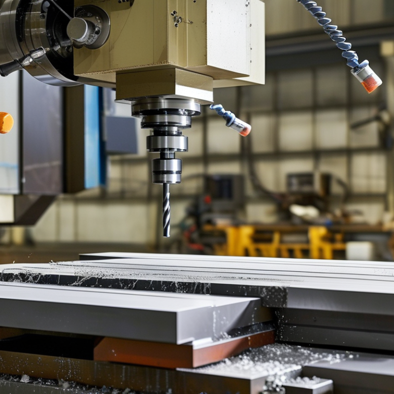
| Spindle | Rotates the cutting tool around its axis | A motor drives the spindle, which holds the cutter in a tool holder or arbor. | Provides the rotational speed needed for cutting edges to shear material. | Face milling, end milling, slotting, drilling, and contouring |
| Cutting Tool | Rotates while following programmed linear or circular paths | Flutes or inserts engage the workpiece as the tool advances through the material. | Removes chips through repeated shearing and cutting actions. | Cutter selection depends on material, feature geometry, surface finish, and cutting depth. |
| Worktable and Fixture | Supports and locates the workpiece | Clamps, vises, bolts, or custom fixtures hold the part against cutting forces. | Prevents movement that could cause dimensional errors or tool damage. | Large or heavy components requiring stable, accurately repeatable positioning |
| CNC Control System | Coordinates multiple axes simultaneously | Interprets programmed toolpaths and commands axis position, feed rate, spindle speed, and auxiliary functions. | Controls the exact path and cutting conditions used to produce the part. | Complex profiles, repeat production, 3-axis machining, and simultaneous multi-axis work |
| Feed Rate | Movement of the tool relative to the workpiece | The programmed feed determines how quickly the cutter advances through the material. | Affects chip thickness, cutting time, heat generation, and surface finish. | Adjusted according to tool diameter, material, spindle speed, and required finish |
| Depth of Cut | Vertical engagement of the tool with the workpiece | Material is removed in one or more passes rather than necessarily in a single cut. | Balances removal rate with spindle power, tool strength, rigidity, and surface quality. | Roughing uses heavier passes; finishing uses lighter passes for improved accuracy. |
| Coolant and Chip Management | Fluid delivery and chip evacuation | Coolant, air, or mist may reduce heat and carry chips away from the cutting zone. | Helps protect the tool, improve surface finish, and prevent chips from being recut. | Long machining cycles, deep pockets, heat-sensitive materials, and high-volume chip removal |
| Typical Machining Sequence | Position, engage, cut, retract, and inspect | The machine establishes work coordinates, approaches the part, removes material, and repeats passes until the target geometry is reached. | Transforms a stock block, plate, or casting into a specified shape and size. | Roughing, semi-finishing, finishing, drilling, tapping, and dimensional inspection |


 © Copyright 2020 Tianjin Tanghaidongyang Valve Co., Ltd. All Rights Reserved.