| 1. Correct series-cell configuration | A common 16-series (16S) LFP pack has a nominal voltage of about 51.2 V, using 3.2 V nominal per cell. | The BMS cell-count configuration must match the battery pack. A mismatch can cause incorrect voltage protection and charging behavior. | Confirm the BMS supports the pack’s exact series count and the inverter’s battery-voltage range. |
| 2. Cell-voltage protection | Many LFP cell specifications list 3.65 V per cell as an upper charging-voltage limit. The cell manufacturer’s limits take precedence. | Per-cell monitoring can detect an individual cell reaching its voltage limit before the overall pack voltage appears abnormal. | Check configurable overvoltage and undervoltage thresholds, measurement accuracy, and recovery behavior. |
| 3. Balancing suited to the pack | BMS designs may use passive balancing, which dissipates excess energy as heat, or active balancing, which transfers energy between cells. | Balancing helps keep cell voltages aligned; it does not increase the cells’ rated capacity or replace proper charging limits. | Review balancing start conditions, balancing current, and whether balancing operates during charging, standby, or both. |
| 4. Current protection matched to the system | Allowable charge and discharge current depends on the cells, pack wiring, busbars, inverter, and protective devices; there is no single suitable rating for every system. | Solar charging and inverter loads can impose different current demands. Protection must be coordinated with the complete system. | Compare continuous and peak current ratings with the battery and inverter specifications, and verify short-circuit protection requirements. |
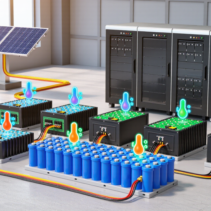
| 5. Temperature monitoring and charge limits | Charging temperature limits are cell-specific. Many standard LFP cells are not to be charged below 0°C (32°F) unless the cell specification explicitly permits it. | Outdoor and unheated installations may encounter temperatures that require the BMS to stop charging or activate an approved heating system. | Check sensor placement, low- and high-temperature cutoffs, and any permitted heater-control function against the cell datasheet. |
| 6. Verified inverter communications | Battery systems may use CAN or RS-485 communications, but using the same interface does not guarantee protocol compatibility. | Correct communication can provide battery limits and status to a compatible inverter; unsupported protocols may prevent reliable coordination. | Verify the exact protocol, wiring, firmware requirements, and supported charge/discharge settings for the intended inverter. |
| 7. Useful monitoring and fault records | Depending on the design, a BMS may report cell voltages, pack current, temperature, state estimates, alarms, and protection events. | Clear monitoring can help identify imbalance, temperature issues, or protection trips that affect system availability. | Check which data are available locally and remotely, how alarms are retained, and whether access works without cloud connectivity. |



 © Copyright 2020 Tianjin Tanghaidongyang Valve Co., Ltd. All Rights Reserved.